
Brett
October 2019
Brett is a fire detection and mapping drone I built in early 2020. It was done as part of the NXP Hovergames Challenge on Hackster.io. The drone is capable of flying autonomously along a predefined area, while taking photos and infrared readings, that get stitched together into one final picture. This definitely is one of the more ambitious hardware projects I've attempted.
This project was motivated by the record-breaking bushfires that were going on in early 2020. Brett helped me discover a suite of open-concept drone platforms:
- PX4: PX4 is the Professional Autopilot. Developed for industry and academica, this is an oben source platform that powers autopilot for vehichles racing from drones to rovers to submersibles.
- QQGroundControl: This ground control station provides full flight control and mission planning for MAVLink enabled drones. It's cross platform and supports multiple autopilots.
- HGDRONEK66: An all-inclusive package (minus batteries) for building your own development drone. It's quite cheap, especially if you can get subsidized as part of a contest.
The key eye-opener for this project is that I realized that drone technology is now accessible enough that anyone can build and program their own flying projects using off-the-shelf components, for $300 or less.
Demo video
Flight video
Tutorial
I'll actually cover the build process for the project, in tutorial format. If you get the parts, you could replicate this!
The project
Our solution is to build a drone-based forest fire charting system, that is capable of flying through a predefined path autonomously. The benefits of this approach is that it is relatively cost-effective, while still allowing for a good resolution with a high degree of control. Most importantly, the data captured by drones on site is very time-relevant, as it can be retrieved as soon as the drone completes its flight mission.
The project, BRETT, consists of two main parts:
-
The drone captures images of the area below it at a constant rate, and stores it in an SD card. Then, the data is stitched together, and cropped to a proper rectangular shape using Python OpenCV. This provides the visual map that firefighters and rescue teams can use to determine where the fire is, relative to landmarks such as towns.
-
The drone captures infrared readings from the position below it at a constant rate, and stores the value along with a timestamp and GPS position in an SD card. This data is then reconstructed using Python Numpy to create a heatmap of measured infrared emissions with respect to position.
The heatmap is then overlayed on top of the stitched aerial image, to create an intuitive view of the current status of the forest fire.
1. Assembling the drone
The majority of the hardware parts are included as part of the HoverGames drone development kit. The kit contents included the drone frame, the brushless motors and rootrs, the basic tools, the NXP Flight Management Unit (FMU), PixHawk GPS module, radio controller, telemetry radios, debuggers, an NXP Rapid IoT device, a Melexis IR sensor, and a 3S/4S battery charger.


Unpacking pictures
Not included items:
The kit does not include a few important items. Specifically, I bought the following separately:
- Zip ties (which have been used a lot on this project!)
- 3S 11.1V 5000mah battery (the drone uses an XT-60 port, so you may need an adapter based on the battery you got)
- Raspberry Pi Zero W
- SD card for the Raspberry Pi
- Raspberry Pi Camera
I followed the hardware assembly exactly as described on the HoverGames documentation, specifically the sections listed below:
- Assembly
- Radio Controller Setup
- Programming FMUK66 for first use
- PX4 configuration using Qgroundcontrol
Here are some pictures of the final product:


2. Image capture on the raspberry pi
Although the kit included a Pixy2 smart vision camera, it turned out to be unsuitable for the project. The camera focuses on object and feature tracking, and its resolution was not high enough to take photos of the landscape from a high altitude. As such, we decided to use a PiCamera, which offered a 5MP resolution in a very to use interface.
Given the use case of the drone in the field, the Pi would need to be run headless and without any external SSH connection. So I set up the Pi Zero so that it could capture photos at regular intervals, and controlled headless without ssh.
The way this was done was by programming the Raspberry Pi so that it supported control by GPIO pins. Here's how it was done:
The raspberry pi runs a preset python script at boot. The user connects a jumper wire between BCM pins 16 to 21 to start image capture. The pi creates a new directory to store the images, and automatically captures images every 2 seconds. The pi stops capture whenever pins 16 and 21 are disconnected, and captures in a new directory whenever they are reconnected. The pi stops capture and safely shuts down when BCM pins 20 and 21 are connected. Here's how to properly set up a new Raspberry Pi Zero W:
-
Flash Raspbian on to an SD card using Balena Etcher as outlined here.
-
Insert the SD card in your computer. Open the /boot directory, and create an empty file named ssh. This allows the Pi to enable SSH connection when it boots up.
-
Create a file called wpa_supplicant.conf in the same directory, with the following content:
ctrl_interface=DIR=/var/run/wpa_supplicant GROUP=netdev
update_config=1
country=US

network={
     ssid="Your network name/SSID"
     psk="Your WPA/WPA2 security key"
     key_mgmt=WPA-PSK
}
Replace the country code (alpha 2 code), ssid, and psk variables. There is an example wpa_supplicant.conf example on the public github listed below.
This will let the Pi automatically connect to your network, with SSH enabled.
-
Connect the Pi Camera to the Pi Zero using a ribbon cable compatible with the Pi Zero. Insert the SD card, and boot the Pi by plugging it in to a microUSB power source.
-
On your computer, install an SSH client like PuTTY. On your computer, connect to the Pi via SSH by setting the target IP to raspberrypi.local, with the target port set to 20. Once connected, you will be prompted to login. Enter pi as the username, and raspberry as the password.
-
Next, on your computer, git clone the project code at https://github.com/jonxuxu/BRETT. Using an FTP client like Filezilla, connect to the Raspberry Pi, and move the capture.py from the /camera folder on the repsitory to the Documents folder on the raspberry pi;
-
On your SSH terminal to the Pi, run the following:
sudo raspi-config
Select InterfacingOptions, select Camera, and enable the camera.
Now run the following:
sudo apt-get update
sudo apt-get install python-picamera python3-picamera
sudo apt-get upgrade
sudo rpi-update
This updates the Pi and install the python libraries needed for image capture. Then reboot the pi by running:
sudo reboot
The SSH terminal will disconnect so you will need to reconnect to the Pi.
Set up autorun on boot for capture.py by running:
sudo nano /etc/rc.local
In the editor, add the following to the end of the file:
sudo python /home/pi/Documents/capture.py
Now the Raspberry Pi will capture images on boot if BCM pins 16 to 21 are connected, and shutdown if BCM pins 20 and 21 are connected.
Pictures will be stored in the / directory. (just the forward slash)
3. IR sensing on the Melexis
Infrared sensing is done on the Melexis MLX90614 IR sensor, which has been generously provided as part of the contest kit. Connect the sensor to the FMU's I2C/NFC 5 pin connection, using the provided JST cable. Affix the sensor and the RPI using zipties.
We interfaced with the sensor by writing an onboard application on the PX4. Here's the documentation.
The sensor data collection program on the flight management unit was written in C++, using PX4 header files, and stored in the /fmu-programs folder. First, the hg_temp.cpp class was written to get temperature data from the sensor. Then, the module.cpp class was written to create the main program that would run in the background. The program would poll for drone position data, and every 5 seconds if data was received, grab temperature data and write to a text file saved on the microSD. The program could be started and stopped at any moment, and the user could pass a parameter [-n] to indicate where they wanted the data to be saved.
To upload the code to the FMU;
- Power on the drone and FMU by plugging in the battery.
- Connect the other telemetry unit to your computer, via the provided Micro-USB to USB-A cable.
- Build the files in fmu-programs/project_brett
- Launch QGroundControl, upload the new firmware as described here:
Significant challenges were encountered in deploying the code to the drone, as well as writing to the text file without crashing the program. Initially, deploying custom firmware would break the drone’s ability to fly. This was remedied by following the PX4 guide instead of the NXP Hovergames guide and reinstalling the required software natively instead of running a VirtualBox instance. Program crashes due to writing to a text file were partly remedied by using fputs() instead of fprintf().
4. Flight
To test the project with real data, we started a controlled campfire. We turned on the camera and IR capture, and armed the drone. It was then flown manually at first to test the sensors, and then flown automatically with a preplanned flight from QGroundControl.


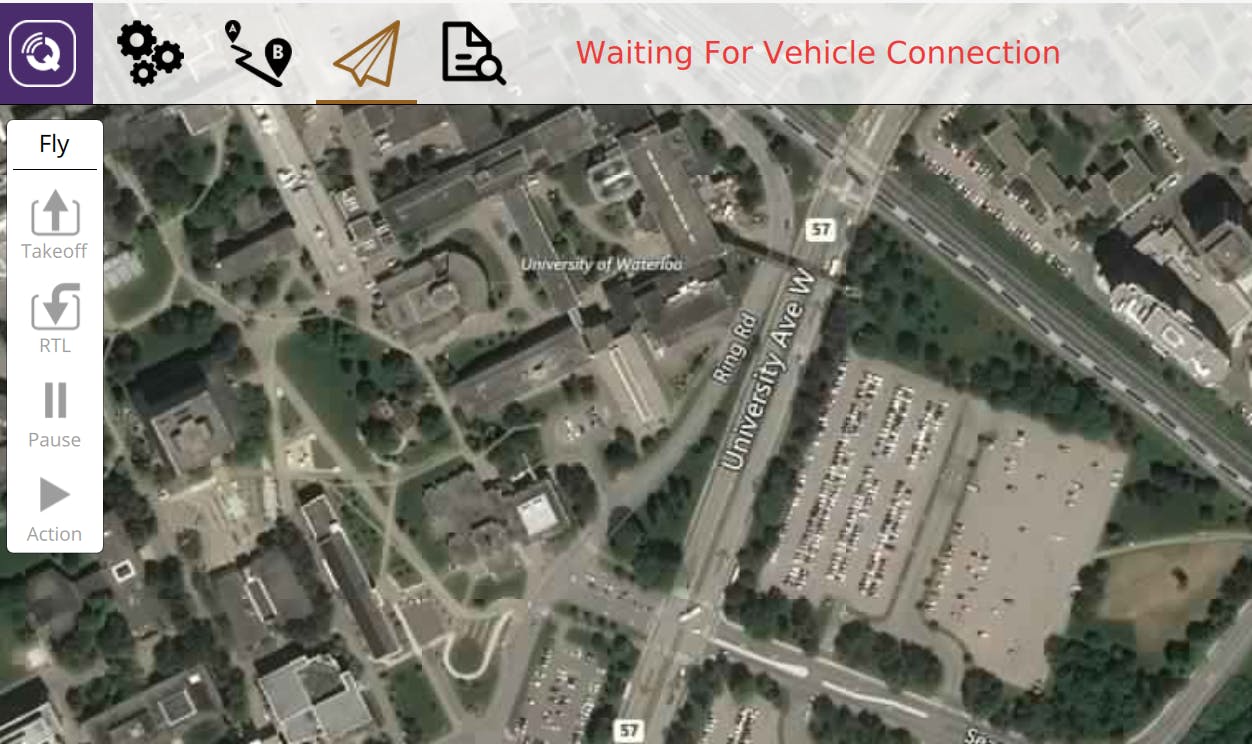
Due to time constraints, we used the QGroundControl flight interface to manually plan a mission for autopilot. We set the waypoiont heights to 20m, and made sure that the path was free of obstacles.
- Click the third icon from the left on the top bar to access mission planning.
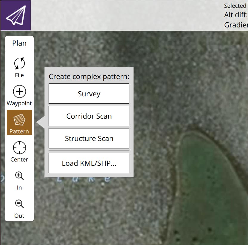
- On the left pane, click Pattern, then Survey
- Drag the waypoints so that you cover the area of interest.
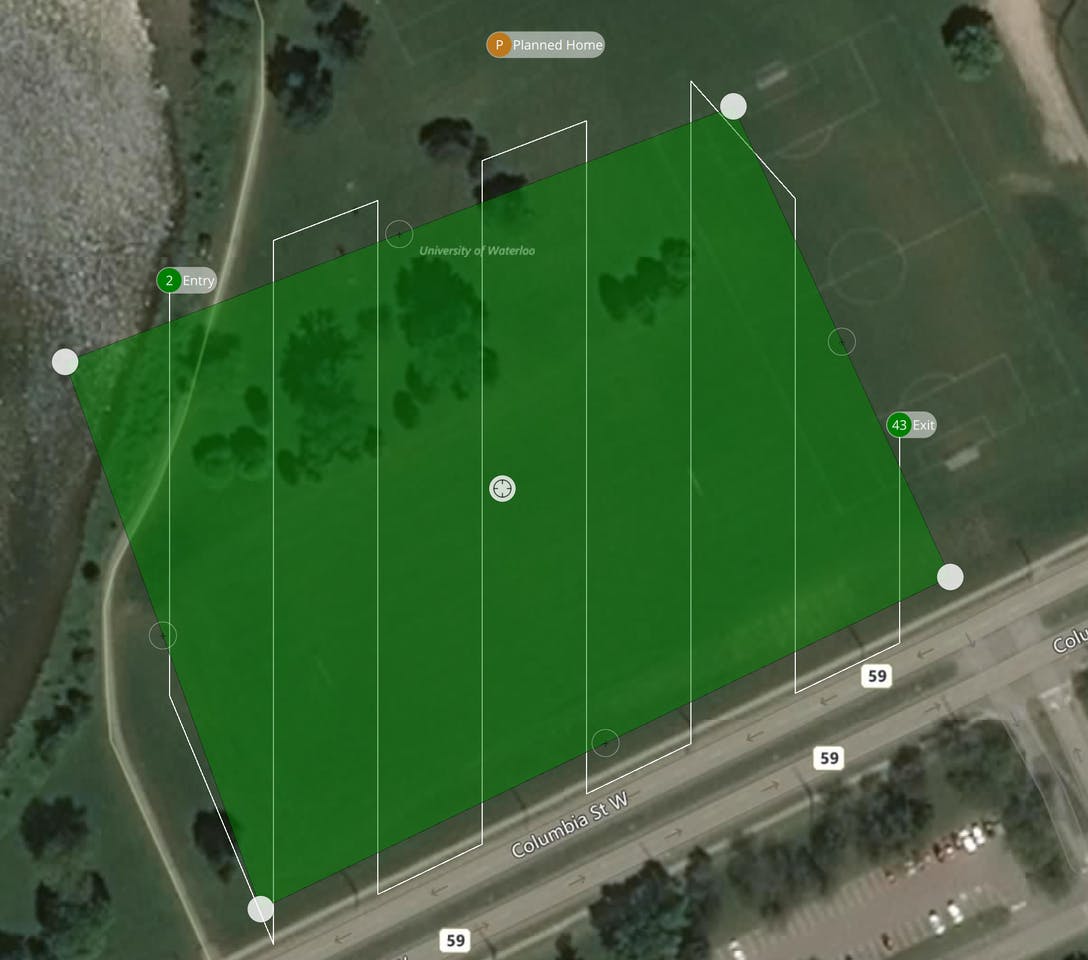
- Set waypoint height to 20 m above the ground, or whatever is suitable for your landscape, and spacing to a distance that is suitable based on the height of your flight path. The higher the altitude of the drone, the wider you can set the spacing. For our project, 10m was a suitable width.
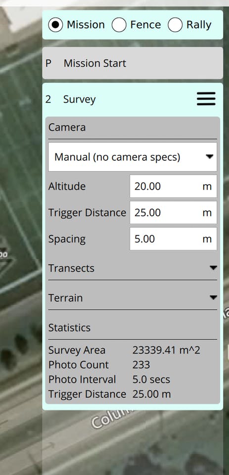
- On the Mission Start tab, select the checkbox next to returntolaunch, so that your drone returns to the launch location after the mission is over.
5. Image stitching and cropping
The image stitching program was written in Python, primarily using the OpenCV library. We used the “createStitcher” and “stitch” methods to combine the images, as well as some helper libraries such as numpy and imutils to make image parsing easier. To combine the heatmap and stitched images, we used the “addWeighted” method from OpenCV to blend the images together. To stitch the images, do the following:
-
Power off the drone and RPI.
-
Copy the IR data and image data from the SD cards in the RPI and FMU to your local computer.
-
Copy the image folder corresponding to your mission of interest, and move it to the /image-stitching folder on your clone of the repository. Make sure you have Python and pip installed, and run the following:
pip install opencv-python
- Open image-stitching.py and replace the inner argument this line:
imagePaths = sorted(list(paths.list_images("1")))
with the name of the your image folder. 5. Stitch the images by running:
python image-stitching.py
- Crop the stitched image by running:
python image-cropping.py --image output.png
6. Heatmap generation
The creation of the infrared heatmap and flight path map was split into three main steps. Firstly, the program had to read in the text file sent to it, which contained information about the drone’s position, as well as ambient and object temperatures. This was done with Python’s built in file in functions. The second task was to parse that information to create a data frame compatible with our graph creating libraries. For the heatmap, it was sufficient to put it into a list, while for the flight path map, the helper function Pandas was used to create and pivot the information. Finally, the formatted data frame was used in conjunction with Seaborn and Matplotlib, two libraries used for data visualization, to create the respective visuals.
Run the following:
pip install numpy
pip install matplotlib
pip install seaborn
Move the test_flight.txt that you copied from the drone's SD card, and move it to the /IRmap folder. Run the heatmap.py program to generate a visualization of the IR readings. The flightpath.py generates a block-based visualization, based on the drone's position.

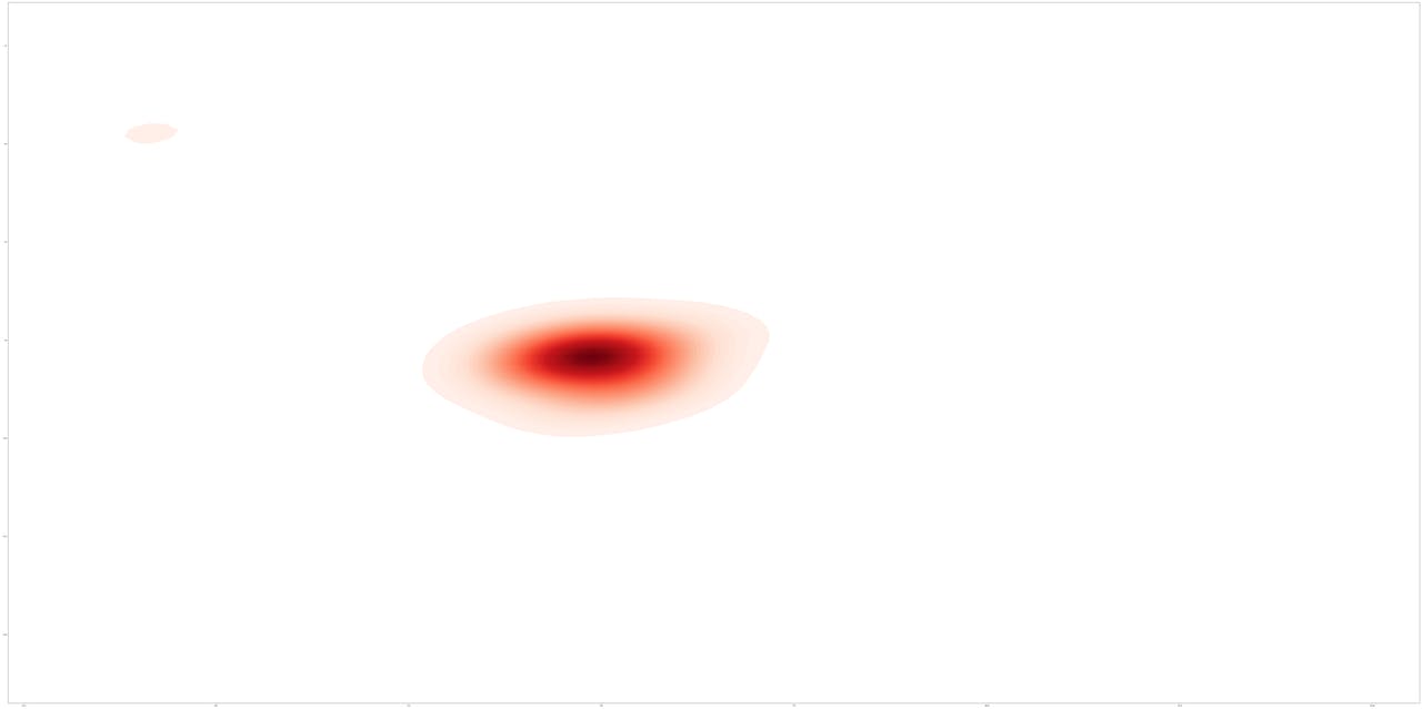


When the IR heatmap is overlayed on the image, we are able to get the final product!
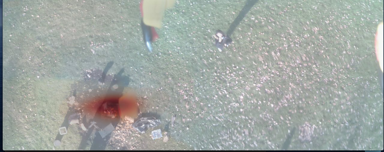
Overall this has been a very challenging project, and we are very happy with how it has turned out. We've been able to create a functional MVP prototype, and with fine tuning and improvements listed below, we think this could be a great solution to the problem of forest fires.
Future work
There are many features we wanted to add, but had to omit due to time constraints. Here are the main improvements we would make to the project in the future:
- Positional capture of image and IR data: Currently, the camera and IR data is captured separately by the drone and the Raspberry Pi, for reasons explained earlier. However, we can connect the pi to the FMU via I2C or SPI (whenever I can find the proper JST adapters for the FMU), and have the FMU ping the pi whenever it has traveled a set distance. Also, the IR sensor can be triggered based on distance instead of time, allowing for a more continuous
- More Extensive Testing: In the interest of time, we were only able to test out our project in a contrived setting, with only one major heat source. In future work, we would like to perform tests in a more realistic setting with multiple large sources of heat. This would give us insights into how we can improve our heatmap generation to be of more use to researchers and fighters.
- Improved User Interface: Currently, our project is not user-friendly and requires us to manually run code. We would like to improve the interface of our application to appeal to people with no technical background. Creating an app that allows users to control the drone’s flight and image capture, while running image stitching and heatmap creation on the backend, would be a pragmatic improvement to our current design.
- Upgrade Hardware: The current infrared sensors and PiCamera mounted on the Raspberry Pi proved to be limited in their capability to take accurate, usable data. Upgrading to higher quality hardware would improve the quality and level of detail present in the produced heat maps, as we would be able to take a larger volume of more sensitive temperature readings. In addition, higher resolution images would improve the clarity of the produced heatmap and would allow users to visually pinpoint the sources of heat.
- Implement FirePath Prediction: A moonshot goal is to create a Tensorflow model that will be able to predict the directions that a forest fire will spread, given graphical info about the surrounding landscape, and the infrared maps. This will create a huge level of utility for asset protection, warning systems, and firefighting.
I hope you found this article insightful. I'll update this article when new features will be added.
Code
Github: https://github.com/jonxuxu/BRETT